Crush ribs for M3 screws in 3D prints
To screw 3D printed parts together I’m mainly using M3 bolts. Up to now I’ve been using embedded M3 nuts to receive these bolts in 3D printed parts. The main advantage are that these are both strong and reusable.
They do require extra parts in the form ot nuts. And also the cavities to receive them which can be difficult to make.
Modelling crush ribs
Sometimes though, it is only necessary to fix parts together once.
While it is possible to screw metric screws into undersize holes, this is often pretty hard because it generates a lot of friction.
The design better holes video from Slant 3D was the original inspiration for using “crush ribs”. That video uses lots of ribs which makes for a complicated geometry.
A video on the made with layers channel supplied the concept of using a STEP file as a “negative space” to carve out a hole with the required ribs. It also shows the crush ribs concept with only three ribs, which is both necessary and sufficient to locate the bolt in the hole.
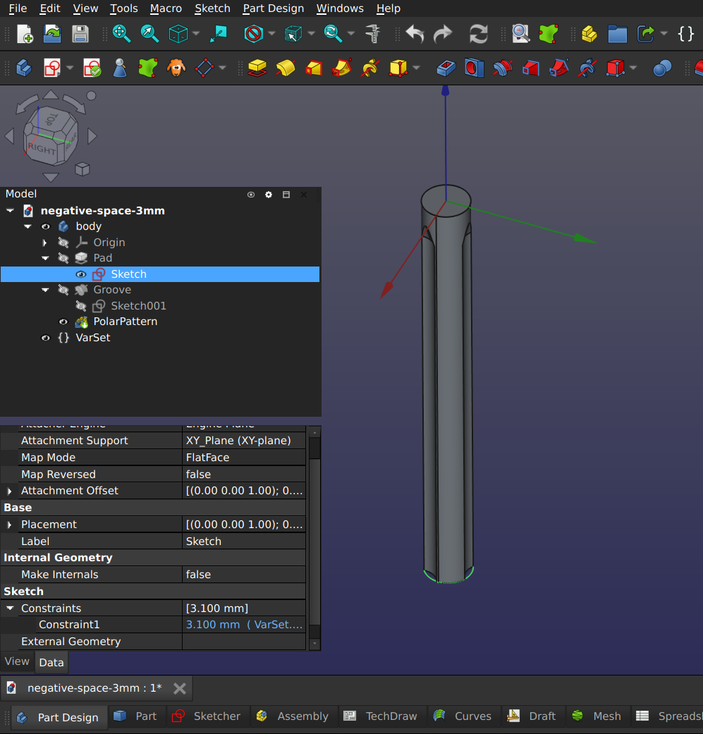
So I modelled the negative of a slightly oversize hole (⌀3.1 mm for M3 thread) in FreeCAD. Three ribs that bulge in toward the core diameter of the thread (⌀2.4 mm) are modelled as revolves that cut into the cylinder.
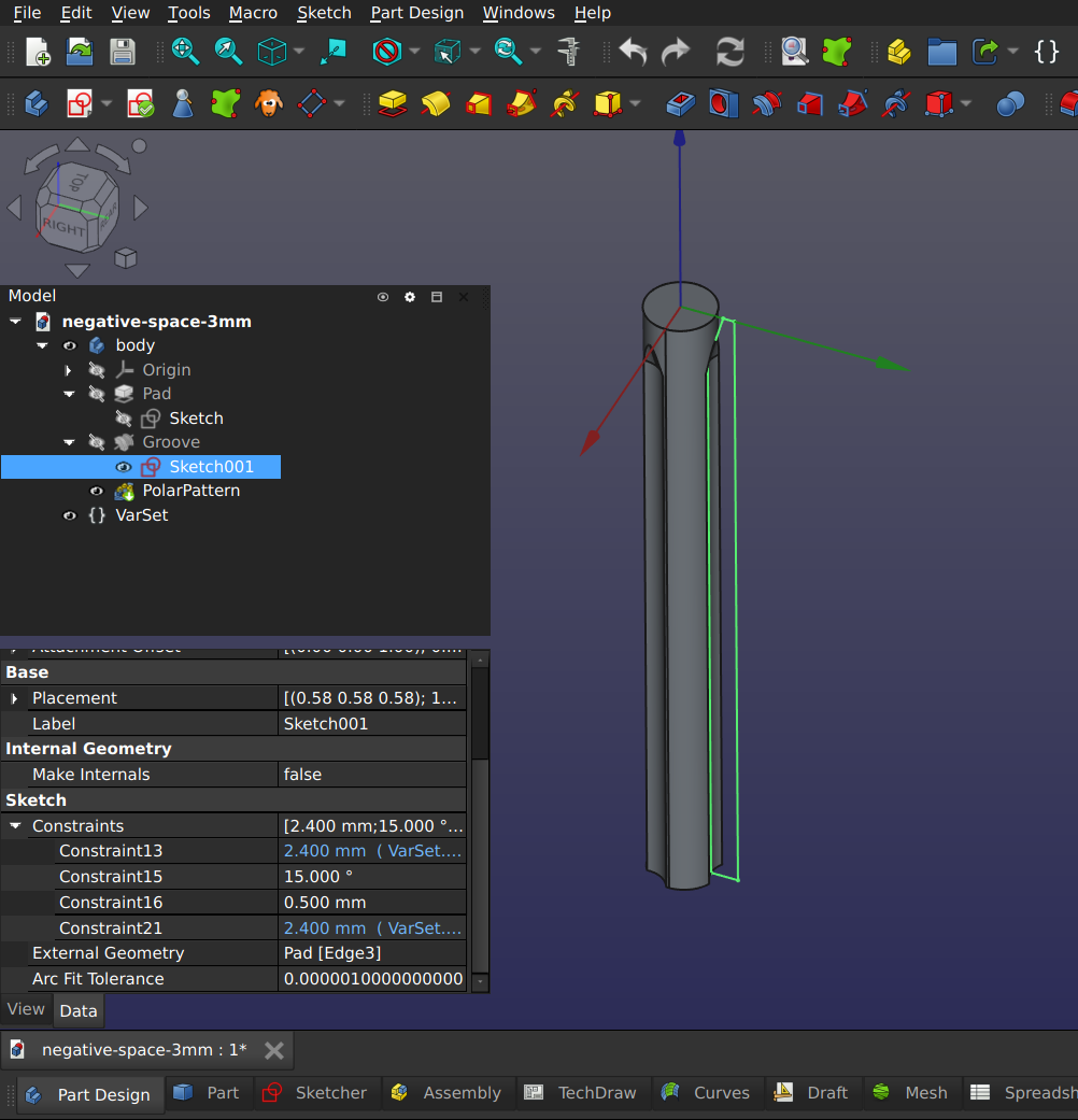
In the sketch shown below, this diameter is modelled as construction geometry. The size of the bulges should be tuned for each thread size because for larger thread sizes a lot more plastic would have to be displaced.
There is definitely a trade off between strength and friction since both are driven by engagement depth of the thread and number of ribs.
The bulges themselves have a diameter that is equal to inner diameter of the M3 screws. This diameter was chosen because it looks right and makes it easy to make the original negative space parametric.
The constraints shown in blue in the previous two images are variables that are part of a “VarSet” defined in the FreeCAD part.
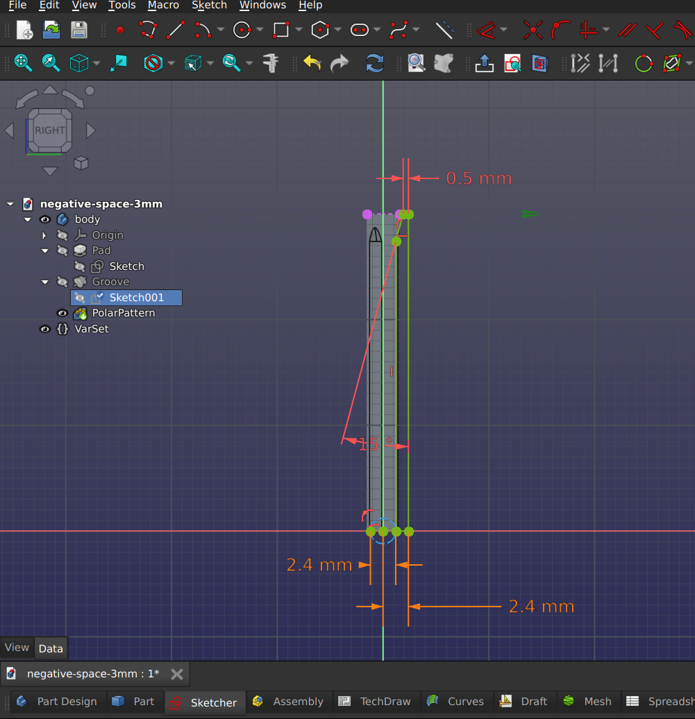
After some tests, this seems to strike a decent balance between friction and holding power for M3 screws. Since this part is defined as parametric, it would be easy to modify it for different diameters.
Note that the crush ribs do not start at the beginning of the hole to make starting the screw easier.
In the spirit of sharing, I’m making both the STEP file and the FreeCAD file for the negative space for an M3 bolt available.
Using a STEP file as a negative space model for a hole
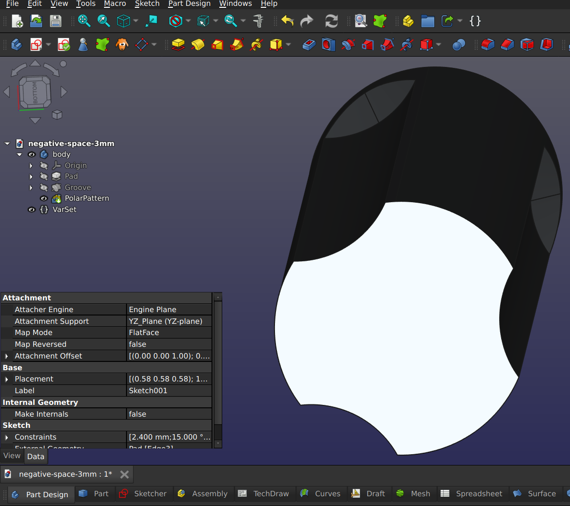
After exporting the geometry as a STEP-file, I modelled a part to receive such a tread.
After importing the STEP file into that file, I selected the imported geometry and created a subshape binder of it in the part.
This subshape binder was used to create the hole using a Boolean cut.
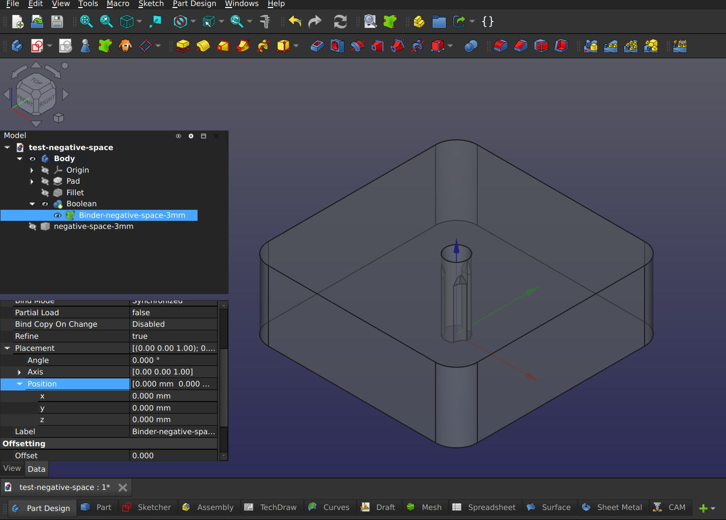
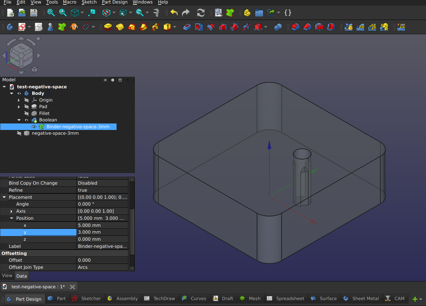
Using the placement parameters of the subshape binder it is possible to move it to whatever place is desired.
For comments, please send me an e-mail.