Dimensional accuracy of 3D prints
In the process of determining the fit for a drill bushing, I measured the relevant dimensions of the test piece.
The results were interesting enough to warrant its own blog post.
Dimensions
To recap, here is a drawing with the dimensions.
The hole diameters are listed above the holes.
Given that this is a rectangular block and that it is mostly symmetric makes this a decent candidate for measurement.
Measuring
For measurements, I’m using my Vernier caliper.
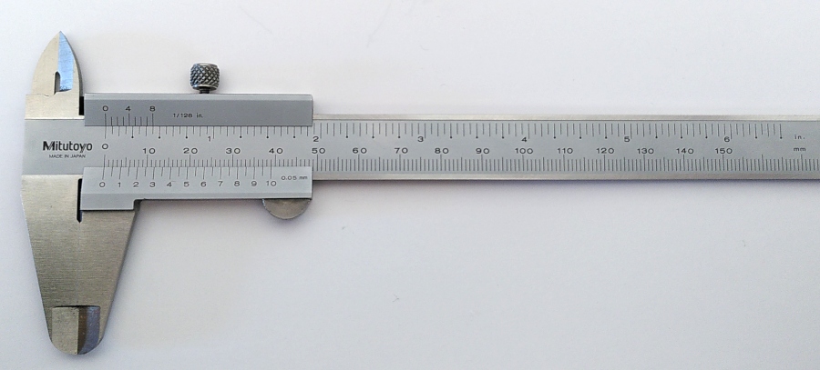
The jaws on the bottom are used for outside dimensions, the jaws on the top for inside dimensions. Measurements will be done in millimeters.
Results for the original print
The original print was made directly from the CAD model.
The diameters of the holes are as follows;
| Nominal | Measured | Deviation |
|---|---|---|
| [mm] | [mm] | [%] |
| 14.8 | 14.65 | -1.0 |
| 14.9 | 14.70 | -1.3 |
| 15.0 | 14.90 | -0.7 |
| 15.1 | 14.95 | -1.0 |
| 15.2 | 15.00 | -1.3 |
Followed by the outside dimensions;
| Nominal | Measured | Deviation |
|---|---|---|
| [mm] | [mm] | [%] |
| 110 | 109.7 | -0.3 |
| 30 | 29.9 | -0.3 |
| 22 | 22.05 | +0.2 |
The dimensions 110 mm and 30 mm (which lie in the XY plane of the 3D printer) are about 0.3% undersize. The thickness (in the Z direction of the printer) is 0.2% oversize.
Evaluation of the original print
The deviation on the thickness of the print is also the resolution of the caliper, which is also close to the accuracy of the caliper. In any case, I feel that the deviation is small enough not to matter.
In the directions parallel to the bed axes, the print is in the order of 0.3% too small.
The deviation in the holes is significantly larger. This seems to indicate that there are at least two but maybe more factors influencing the deviations.
One obvious one is thermal shrinkage. The material comes out of the nozzle at 235 °C, and solidifies around 220 °C. The bed temperature is 85 °C, which is also the Tg for PETG. This should influence both outside dimensions and inside dimensions in the same direction, making them smaller.
Another would be “squish-out” of the perimeter layers. This would make outside dimensions larger, and inside dimensions smaller. Probably by a set amount influenced by factors like nozzle size, layer height, flow rate and others.
Experiment with scaled print
In FreeCAD, I used the “SubShapeBinder” tool to capture the shape of the original part. This was then scaled using “Scale” tool from the “Part” workbench.
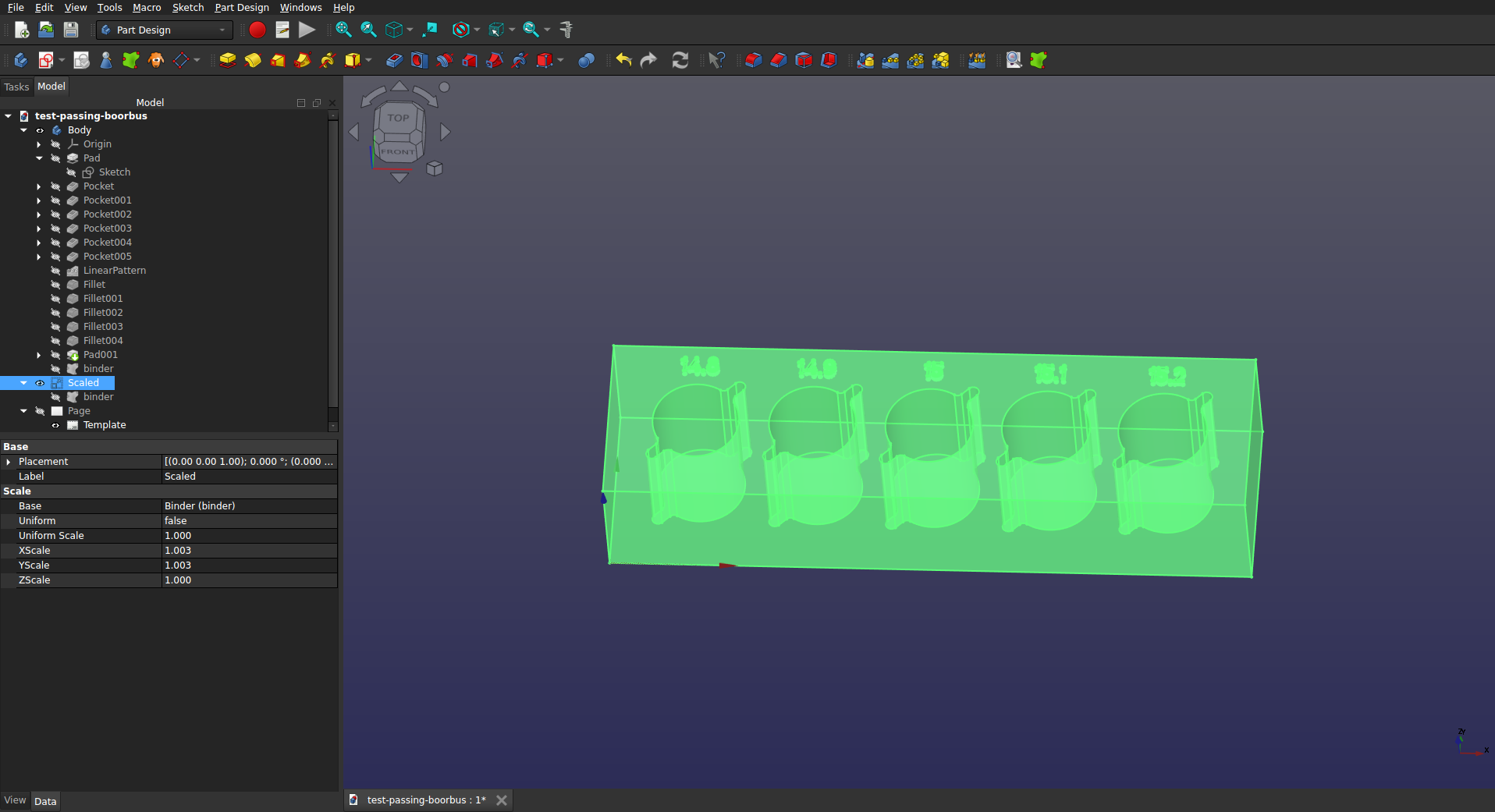
The chosen scaling factors were 1.003 in X, 1.003 in Y and 1 in Z. To do this, I first had to set “Number of decimals” in “General” preferences to three.
The scaled part was exported as a STEP-file, which replaced the original STEP file in the PrusaSlicer project. It was sliced and printed with the same settings as the original.
The scaled part was then also measured. A comparison of the dimensions of the original and scaled print is shown below.
Holes:
| Nominal | Original | Scaled |
|---|---|---|
| [mm] | [mm] | [mm] |
| 14.8 | 14.65 | 14.70 |
| 14.9 | 14.70 | 14.80 |
| 15.0 | 14.90 | 14.85 |
| 15.1 | 14.95 | 14.95 |
| 15.2 | 15.00 | 15.05 |
Outside dimensions;
| Nominal | Original | Scaled |
|---|---|---|
| [mm] | [mm] | [mm] |
| 110 | 109.7 | 110.1 |
| 30 | 29.9 | 29.95 |
| 22 | 22.05 | 22.05 |
For the outside dimensions of this part, the scaling in X (dimension 110) should be reduced to 1.0027, while the Y direction (dimension 30) should be increased to 1.0033.
The exact scaling factors will depend on the material and the print conditions used. Even the individual printer used might be important because of things like belt tension and general wear.
Note that global scaling is not sufficient to compensate for the deviations in the hole dimensions.
Conclusions
3D FDM prints need scaling for optimal accuracy. You should be able to get to within ±0.1 mm (±0.004”) of overall nominal dimensions at the cost of one extra print and the time to measure it. For most applications of 3D printed plastic parts, that should be more than accurate enough.
If you need more accuracy, 3D printed plastic is probably not going to be rigid or strong enough anyway.
For printing PETG on my Prusa MK4S, a scaling factor of 1.003 in X and Y seems to be a good starting point. For relatively small parts, the Z direction does not require scaling.
Global scaling is not sufficient to create accurate size holes. Holes need to be slightly oversized (0.1−0.2 mm) for a loose or sliding fit. With relief slots in the holes, a nominal sized hole will result in a slight interference fit.
For comments, please send me an e-mail.