Meshing a circle with hex elements in CalculiX
In this article a methd of creating a second order hex mesh for circular cross-sections will be shown.
Circle quadrant
In this method, the circle is basically divided into four quadrants. Therefore a method to generate a quadrant will be shown first.
The code to generate a circle quadrant in the XY plane, extruded in Z is shown below:
## Define the view.
rot y
rot r 135
rot u 30

## Dimensions
# Radius
valu R / 50 1000
# Starting height
valu zs / 0 1000
# Thickness
valu z / 6 1000
# divisions
valu dl 24

## Geometry
pnt pq1 0 0 zs
pnt pq2 R 0 zs
pnt pq3 0 R zs
# Central lines
line lq1 pq1 pq2 dl
line lq2 pq1 pq3 dl
# Arc
line lq3 pq2 pq3 pq1 dl
surf sq1 blend lq1 lq2 lq3
seta Face1 s sq1
comp Face1 do
swep Face1 Face2 tra 0 0 z

## Generate mesh
elty all he20r
mesh all

## Create image
capt Circle quadrant generated by cgx.
view elem
plus ld all
frame
zoom 0.7
hcpy png circle-quadrant
# Use ImageMagick to trim off the white edges.
sys mogrify -trim circle-quadrant.png
The generated image is shown below.
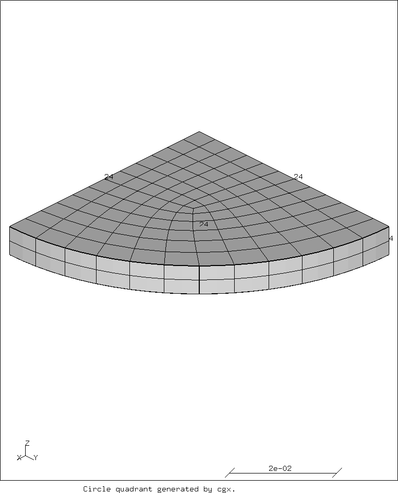
Note how the line divisions are equal for both the lines and the arc. This seems to work the best. Since we are using second order elements, divisions should be a multiple of four. Most numbers divisible by four work for the divisions. Use a higher number for a finer mesh.
Full circle
Instead of one quadrant, four quadrants are now generated:
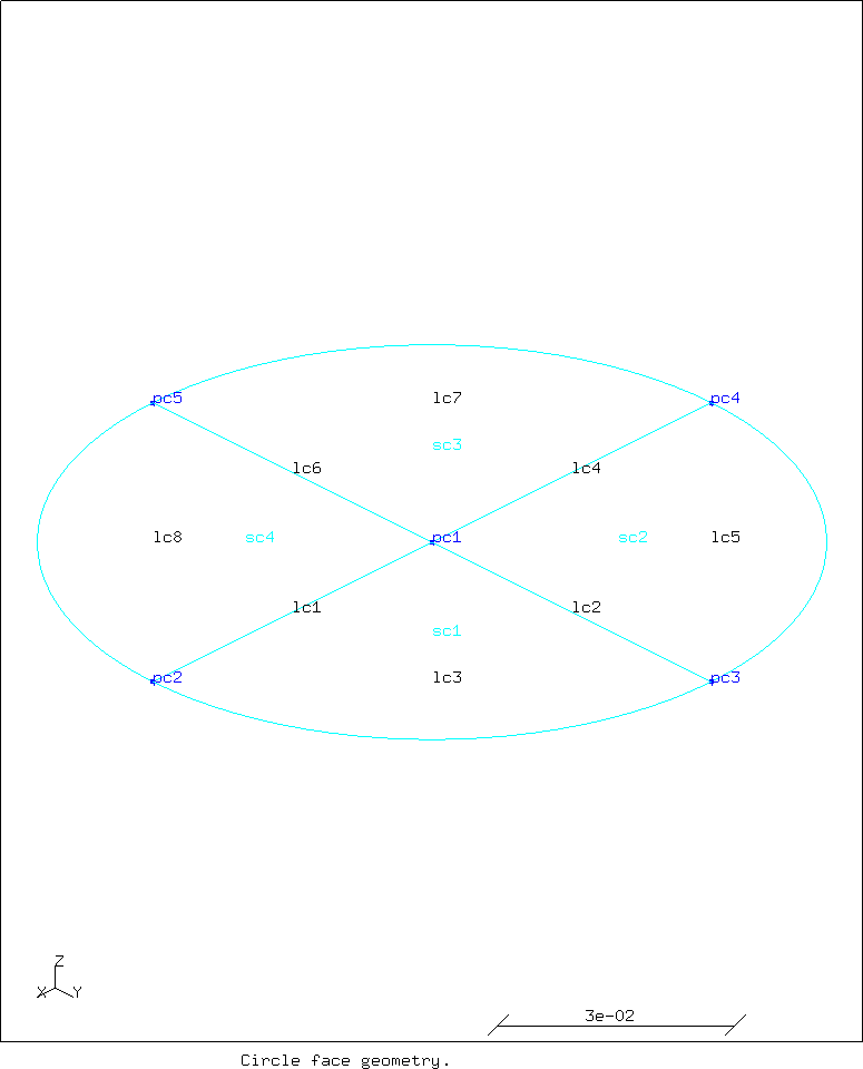
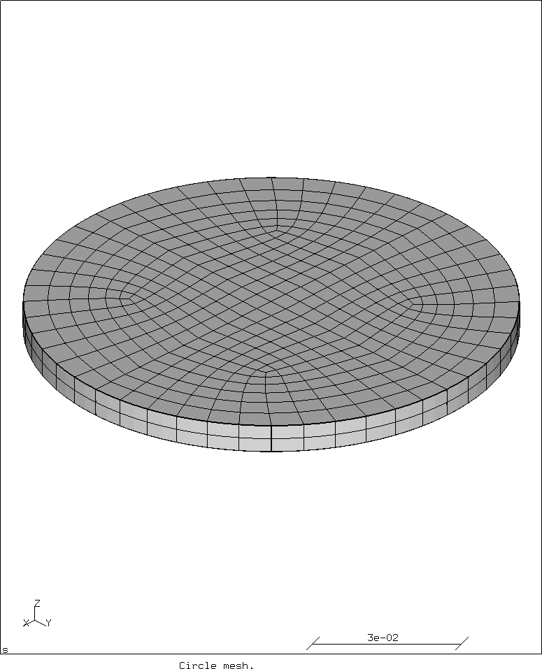
## Dimension
# Radius
valu Rc / 50 1000
valu nRc - 0 Rc
# Starting height
valu zsc / 0 1000
# Thickness
valu tc / 6 1000
# divisions
valu dlc 24

## Geometry
pnt pc1 0 0 zsc
pnt pc2 Rc 0 zsc
pnt pc3 0 Rc zsc
pnt pc4 nRc 0 zsc
pnt pc5 0 nRc zsc
line lc1 pc1 pc2 dlc
line lc2 pc1 pc3 dlc
line lc3 pc2 pc3 pc1 dlc
line lc4 pc1 pc4 dlc
line lc5 pc3 pc4 pc1 dlc
line lc6 pc1 pc5 dlc
line lc7 pc4 pc5 pc1 dlc
line lc8 pc5 pc2 pc1 dlc
surf sc1 blend lc1 lc2 lc3
surf sc2 blend lc2 lc4 lc5
surf sc3 blend lc4 lc6 lc7
surf sc4 blend lc6 lc1 lc8
seta facec1 s sc1 sc2 sc3 sc4
comp facec1 do
seto cylc1
swep facec1 facec2 tra 0 0 tc
setc

## Show the geometry before extrusion.
valu showgeom 1
if showgeom > 0
capt Circle face geometry.
plot pa facec1
plus la facec1
plus sa facec1
stop
hcpy png circle-geometry
sys mogrify -trim circle-geometry.png
endif

## Display the mesh
valu showmesh 1
if showmesh > 0
capt Circle mesh.
elty all he20r
mesh all
view elem
plot e all n
view surf
stop
hcpy png circle-mesh
sys mogrify -trim circle-mesh.png
endif
This yields the following images. First the geometry.
Next the mesh.
For comments, please send me an e-mail.
Related articles
- Creating a rectangular tube in CalculiX
- Building CalculiX with the PaStiX solver without CUDA
- Element names in Calculix
- FEA based on STEP geometry using gmsh and CalculiX
- Reading CalculiX mesh with Python