Corrugation against buckling
Composite sandwich products loaded in bending tend to fail by buckling of the laminate under compression. The author’s intuition is that corrugating the surface under compression should help. So the question is; does it help, and how much. That is what will be investigated in this article.
Introduction
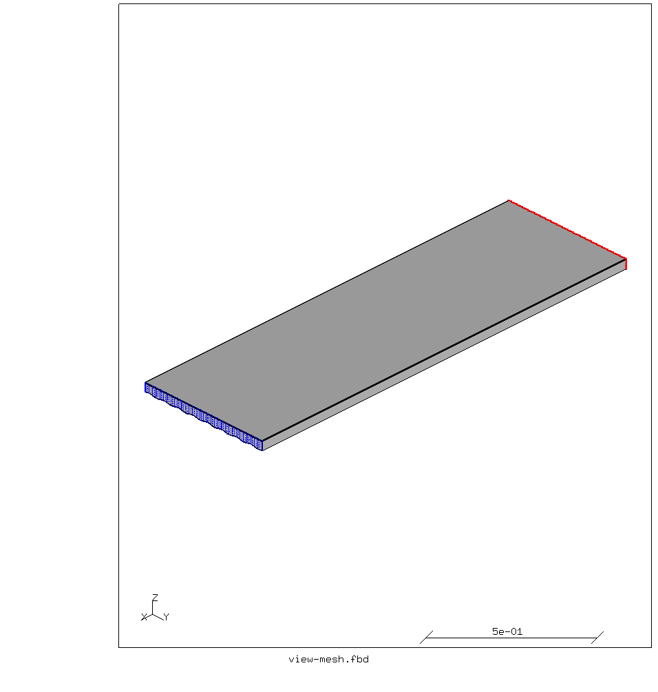
Target of the comparison are two sandwiches, 34 mm thick in total. Both are 1.5 m long, 48 cm wide. The laminates on both sides are 2 mm thick. The core is PMI foam. In one of the sandwiches the bottom laminate is corrugated in a sinusoidal shape with an initial wavelength of 60 mm and amplitude of 5 mm. The laminate is mostly unidirectional carbon fibers with one 200 g/m² woven layer on the outside. The sides of the sandwich are closed with 2 mm thick quasi-isotropic laminates. The cross-sections of both are shown below.
Both sandwiches are clamped at one end and loaded with a identical load (via a rigid body constraint) at the other end.
The behavior under load will be simulated with the CalculiX finite element analysis software, with the geometry being generated by the preprocessor with the help of a Python script to interpolate a sinusoid as a spline.
The meshes are shown below.

The properties of the laminate are as follows:
Generated by lamprop version 2022.06.22
laminate: Mflat
thickness: 1.98 mm, density: 1.51 g/cm³
fiber volume fraction: 56%, fiber weight fraction: 66.6%
laminate weight: 3004 g/m², resin consumption: 1004 g/m²
num weight angle   vf fiber
    [g/m²]   [°]  [%]
1    100     0   56 T700SC
2    100    90   56 T700SC
3    300     0   56 T700SC
4    300     0   56 T700SC
5    300     0   56 T700SC
6    300     0   56 T700SC
7    300     0   56 T700SC
8    300     0   56 T700SC
In-plane engineering properties:
E_x  = 125348 MPa, E_y  = 16102 MPa, E_z  = 13097 MPa
G_xy  = 3780 MPa, G_xz  = 3166 MPa, G_yz  = 3888 MPa
ν_xy = 0.21477
α_x = 2.682e-07 K⁻¹, α_y = 1.815e-05 K⁻¹
Engineering properties derived from 3D stiffness matrix:
E_x = 126081 MPa, E_y = 19069 MPa, E_z = 13783 MPa
G_xy = 3780 MPa, G_xz = 3825 MPa, G_yz = 4639 MPa
ν_xy = 0.186, ν_xz = 0.306, ν_yz = 0.396
** Material data for CalculiX / Abaqus (SI units):
*MATERIAL,NAME=Mbot
*ELASTIC,TYPE=ORTHO
1.291e+11,6.027e+09,2.179e+10,6.048e+09,6.438e+09,1.583e+10,3.78e+09,3.825e+09,
4.639e+09,293
*DENSITY
1514
The breaking strain of the fibers used is at least 1.7%. That means that the tensile strength in the 0° direction is 2140 MPa. For these kinds of laminates, we use the rule of thumb that the compression strength is around 60% of the tensile strength, or -1280 MPa.
Orienting laminate properties
The top laminate is aligned with the global coordinate system used in the FEA. So it needs no special attention.
The planes of the side laminates are at 90° to the XY plane.
So a *ORIENTATION card is needed in the solver input to align the material
properties with the orientation of the laminate.
The corrugated side is more complicated. The elements on that side are curved and their normals point in different directions. Creating orientations for those elements by hand, while possible, would be cumbersome and error-prone. So the author wrote a program for that: auto-orient.
This analyzes the sets of elements it is invoked on, and generates
suitable orientations, element sets and *SOLID SECTION cards.
These can simply be included in the solver job file.
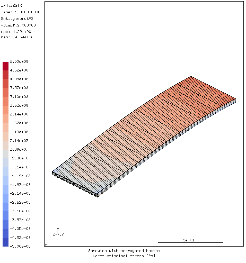
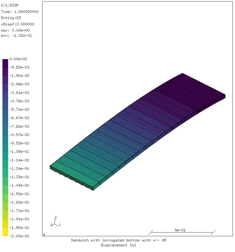
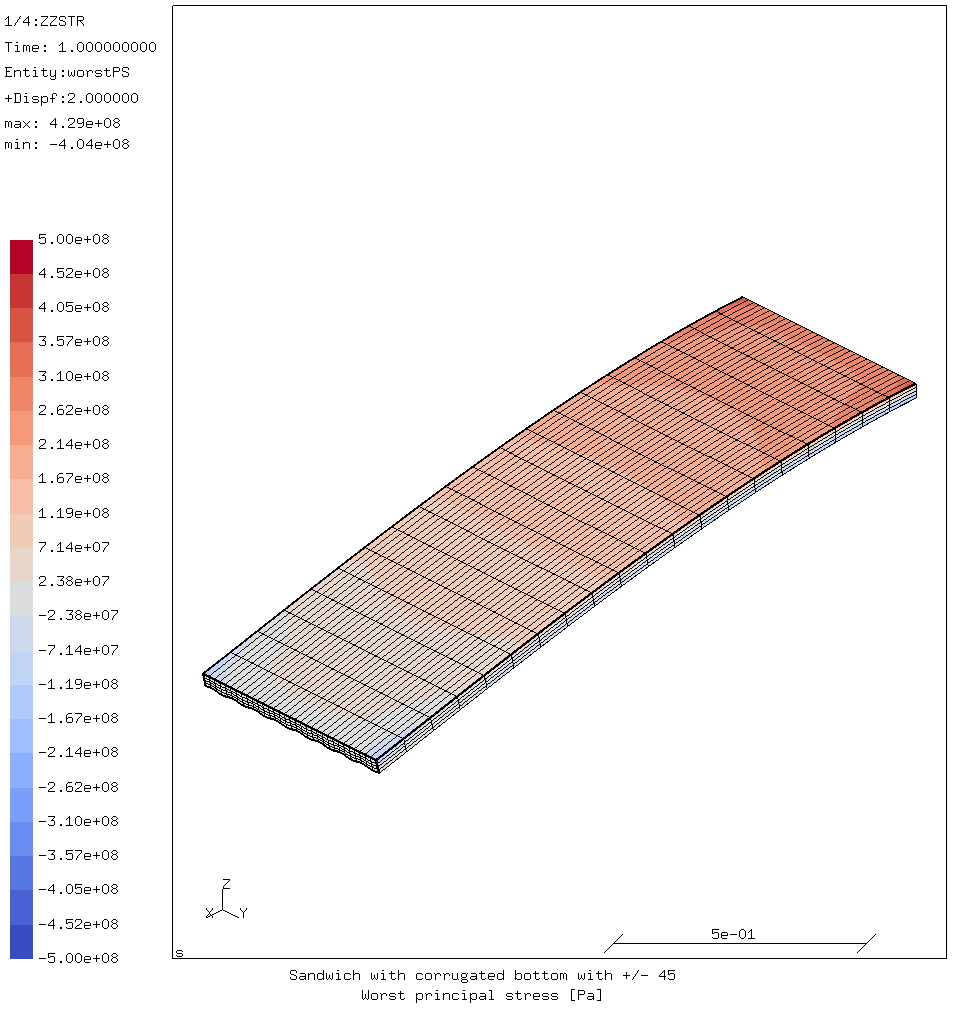
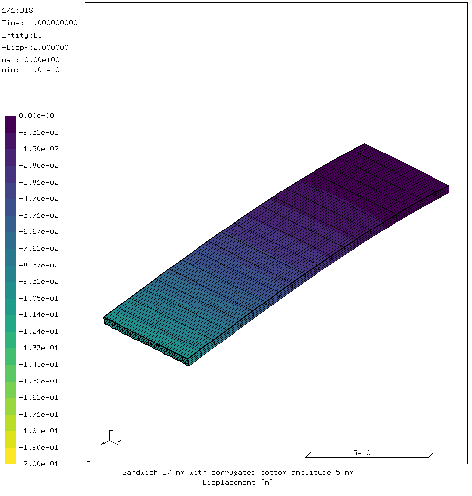
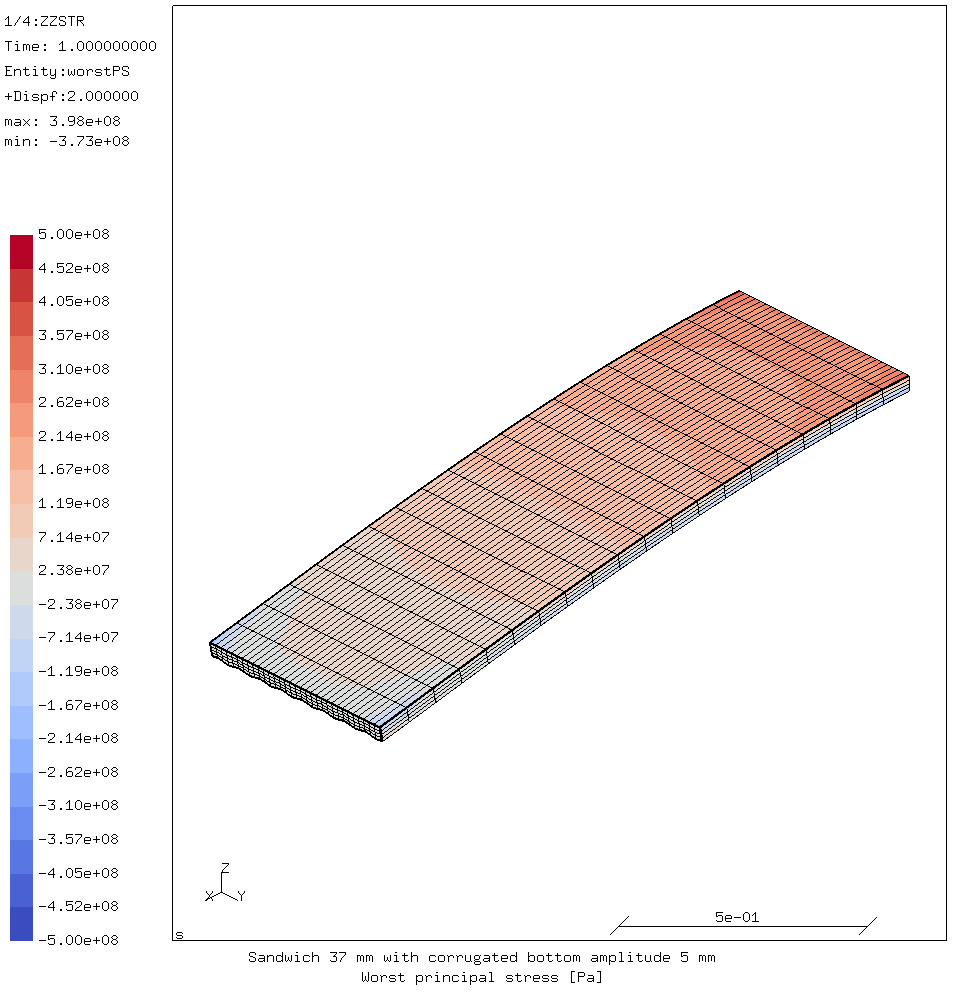
Corrugated version 1 vs flat version 1

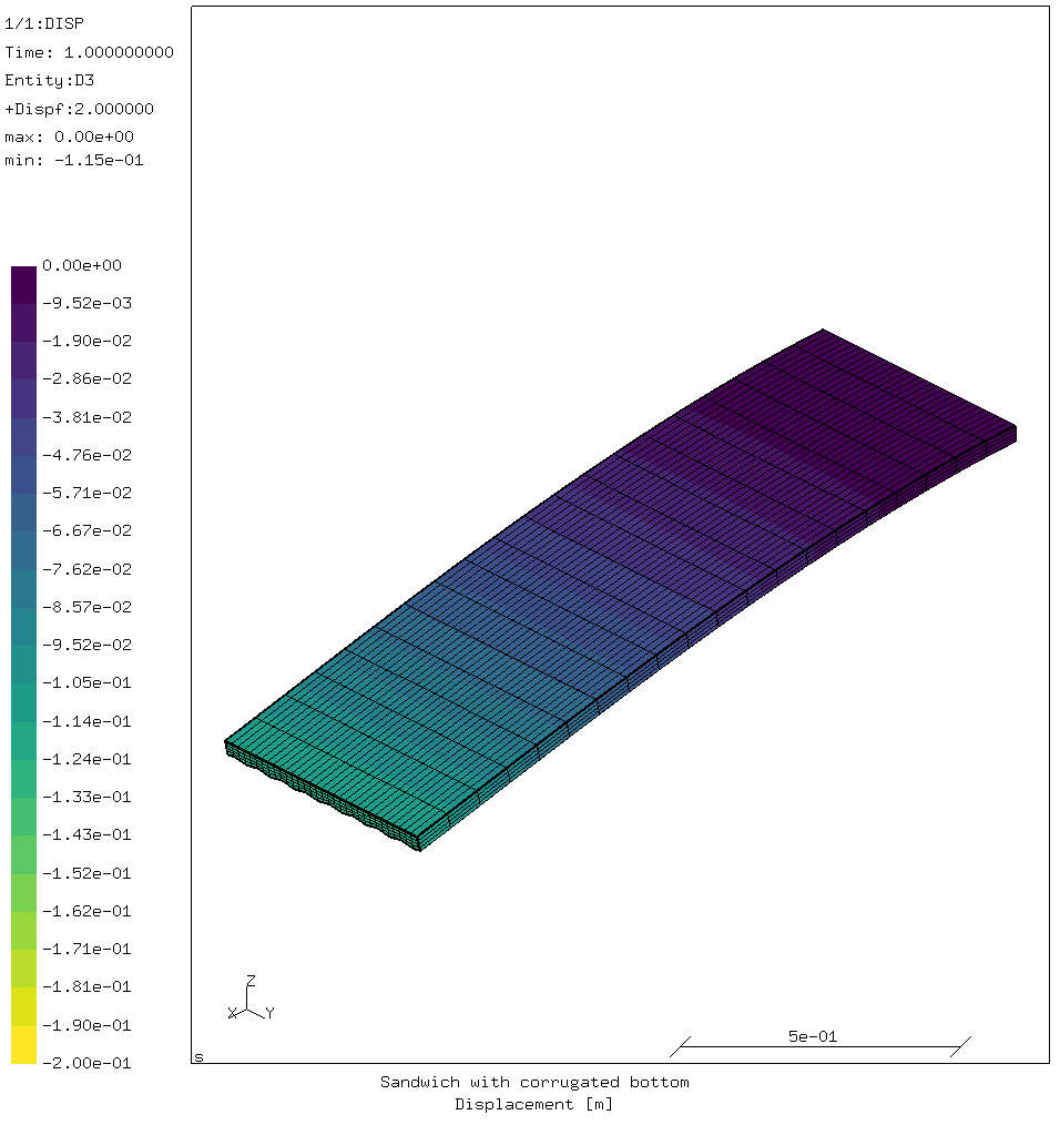
The sandwich with the corrugated bottom deflects more (-115 mm) than the flat-bottomed sandwich (-99 mm). That is to be expected; its cross-section has a lower second area moment because most of the bottom laminate is closer to the top laminate than the flat version.
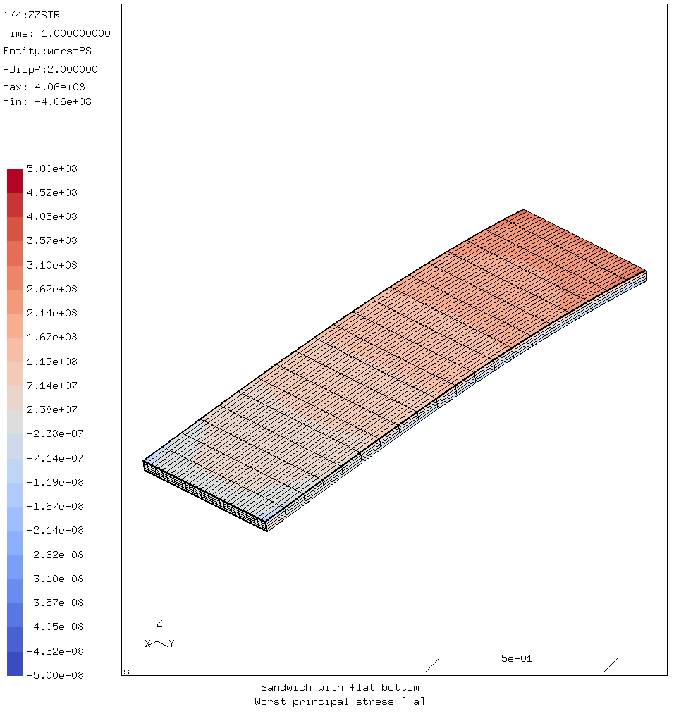
Results for flat1:
| displacement | -98.95 | mm |
| compression stress | -406 | MPa |
| compression stress factor | 3.17 | |
| tensile stress | 406 | MPa |
| tensile stress factor | 5.28 | |
| buckling factor | 2.26 |
Results for corrugated1:
| displacement | -114.79 | mm |
| compression stress | -434 | MPa |
| compression stress factor | 2.96 | |
| tensile stress | 429 | MPa |
| tensile stress factor | 5.00 | |
| buckling factor | 2.50 |
The maximum stresses are higher in the sandwich with the corrugated bottom than those in the regular sandwich. This is also due to the lower stiffness. The ratio between the compression strength and the occurring stress (the compression factor) is therefore higher for the flat panel than for the corrugated panel.
The buckling factor is slightly higher then for the flat panel. But in both cases the buckling factor is smaller than the compression stress factor. So both will fail in buckling.
Corrugated version 2: updated bottom laminate
In the bottom laminate one layer of unidirectional fibers was replaced by a layer of ±45° fiber of equivalent weight.
This has changed the laminate properties from those shown in above to:
Generated by lamprop version 2022.06.22
laminate: Mbot
thickness: 1.98 mm, density: 1.51 g/cm³
fiber volume fraction: 56%, fiber weight fraction: 66.6%
laminate weight: 3004 g/m², resin consumption: 1004 g/m²
num weight angle   vf fiber
    [g/m²]   [°]  [%]
1    100     0   56 T700SC
2    100    90   56 T700SC
3    300     0   56 T700SC
4    300     0   56 T700SC
5    150    45   56 T700SC
6    150   -45   56 T700SC
7    300     0   56 T700SC
8    300     0   56 T700SC
9    300     0   56 T700SC
In-plane engineering properties:
E_x  = 109107 MPa, E_y  = 19647 MPa, E_z  = 13097 MPa
G_xy  = 8358 MPa, G_xz  = 3250 MPa, G_yz  = 3804 MPa
ν_xy = 0.39130
α_x = 4.135e-08 K⁻¹, α_y = 1.377e-05 K⁻¹
Engineering properties derived from 3D stiffness matrix:
E_x = 110279 MPa, E_y = 22902 MPa, E_z = 14148 MPa
G_xy = 8418 MPa, G_xz = 3893 MPa, G_yz = 4571 MPa
ν_xy = 0.349, ν_xz = 0.243, ν_yz = 0.377
** Material data for CalculiX / Abaqus (SI units):
*MATERIAL,NAME=Mcorr
*ELASTIC,TYPE=ORTHO
1.155e+11,1.066e+10,2.609e+10,6.081e+09,6.405e+09,1.583e+10,8.418e+09,3.893e+09,
4.571e+09,293
*DENSITY
1514
The Young’s modulus in the length direction has been reduced significantly. But the shear modulus has been more than doubled.
Displacement and stress images:
Displacement and stress values:
| displacement | -121.54 | mm |
| compression stress | -404 | MPa |
| compression stress factor | 2.78 | |
| tensile stress | 429 | MPa |
| tensile stress factor | 5.00 | |
| buckling factor | 2.87 |
Since the longitudinal stiffness of the bottom laminate has been reduced, it is not suprising that the deflection has been increased.
The buckling factor has been increased from 2.5 to 2.87 with just the one small change to the laminate.
The compression stress factor is now slightly lower than the buckling factor. So this sandwich will likely fail in pure compression rather than buckling.
This bottom laminate will be used for the corrugated laminates from now on.
Flat version 2: changed bottom laminate
To discern how much improvement in the previous alternative was due to the material properties, a sandwich with a flat bottom laminate with a layer of ±45° fiber was also calculated.
Results overview:
| displacement | -104.54 | mm |
| compression stress | -385 | MPa |
| compression stress factor | 2.93 | |
| tensile stress | 405 | MPa |
| tensile stress factor | 5.29 | |
| buckling factor | 2.12 |
The displacement has increased as expected because of the lower longitudinal stiffness of the bottom laminate.
It’s buckling factor is only 2.12. So the corrugation and ±45° layer really have a strong synergetic effect. But the ±45° layer is not really useful for the flat bottom laminate.
Corrugated version 3: increased amplitude
For the next test, the amplitude of the corrugation is changed from 5 mm to 10 mm. The position of the top laminate is adjusted so the total thickness does not exceed 34 mm. The sides of the sandwich are closed with a quasi-isotropic laminate, as before. The cross-section is shown below.
Deflection and stress are shown below.
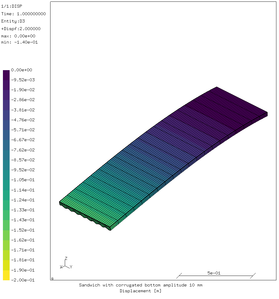
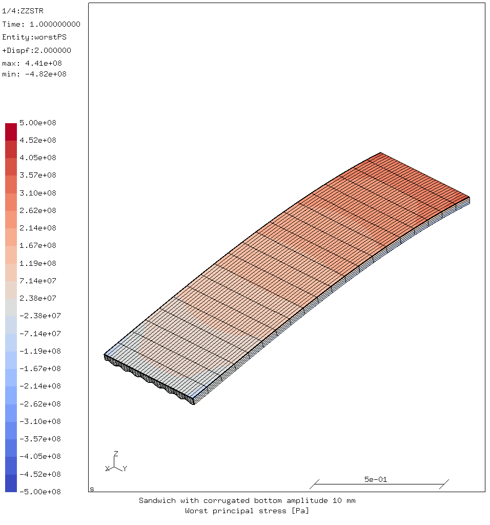
Deflection and stress values:
| displacement | -140.36 | mm |
| compression stress | -482 | MPa |
| compression stress factor | 2.33 | |
| tensile stress | 441 | MPa |
| tensile stress factor | 4.85 | |
| buckling factor | 4.51 |
The deflection is again higher because more of the bottom laminate is closer to the top laminate, leading to a reduced stiffness.
The buckling strength of this sandwich is twice that of the original sandwich, with the same overall thickness.
However in this case the compression stress limit would be reached with a load factor of 2.3, so long before buckling occurs.
Corrugated version 4: thicker sandwich with 5 mm amplitude
In this variant, the total thickness is increased to 36.5 mm so that the middle of the bottom laminate is 34 mm from the top. The amplitude of the corrugation is the original 5 mm.
Displacement and stress images:
Displacement and stress values:
| displacement | -103.92 | mm |
| compression stress | -378 | MPa |
| compression stress factor | 2.98 | |
| tensile stress | 403 | MPa |
| tensile stress factor | 5.32 | |
| buckling factor | 3.14 |
Deflection and stresses are close to the “flat2” variant, which has the same laminate build-up.
The buckling factor is slightly larger than the compression stress factor. So in this case the laminate would likely also fail in compression just before it buckles.
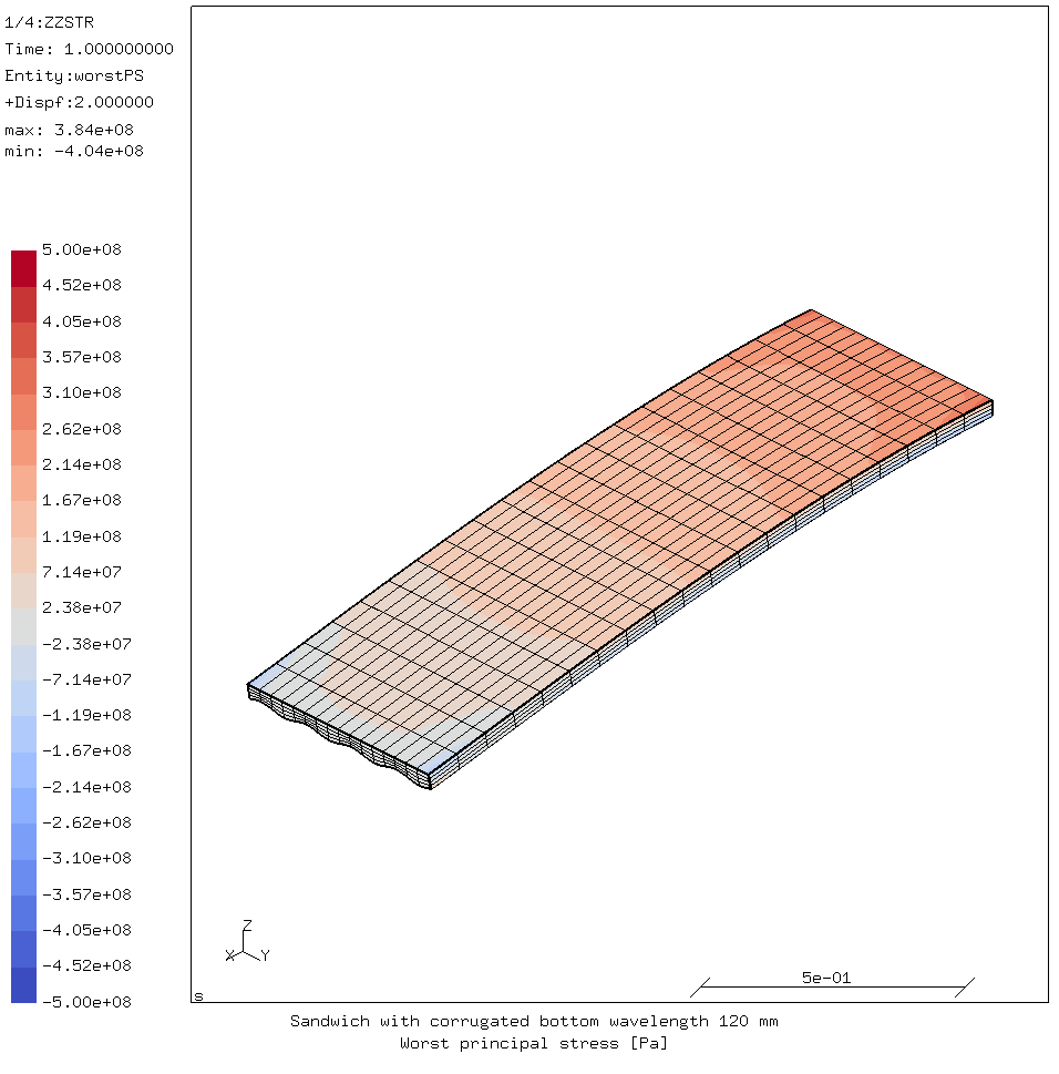
Corrugated version 5: corrugation with 120 mm wavelength
This is a variant on version 2, where the wavelength of the corrugation has been changed from 60 mm to 120 mm.
The amplitude of the corrugation and the total height have not been changed compared to version 1 and 2.
The maximum deflection is -122 mm and the maximum stresses are +424 MPa and -400 MPa. This is similar to corrugated version 2.
However, the buckling factor is only 2.04, which is worse than the flat version 1! So the wavelength of the corrugation has a huge influence, and shorter is better.
So the amplitude will be increased to 13 mm and the total thickness to 40.5 mm.
Displacement and stress images:

Displacement and stress results:
| displacement | -100.26 | mm |
| compression stress | -410 | MPa |
| compression stress factor | 2.74 | |
| tensile stress | 382 | MPa |
| tensile stress factor | 5.62 | |
| buckling factor | 2.97 |
Since buckling factor is higher than the compression stress factor, this sandwich will likely fail in compression. So the larger the wavelength, the larger the amplitude needs to be to generate the desired improvement in buckling strength.
Corrugated version 6: corrugation with 30 mm wavelength and amplitude 3 mm
The question here is what happens is we reduce the wavelength and the amplitude.
The cross-section of this version is shown above. From a standpoint of manufacturability this is not ideal. Getting the fibers from the bottom layers to not bridge over the corrugations will probably require tooling. E.g. heavy metal rods placed in the corrugations in the middle and rolled outwards from valley to valley when putting down each layer.
Displacement and stress images:
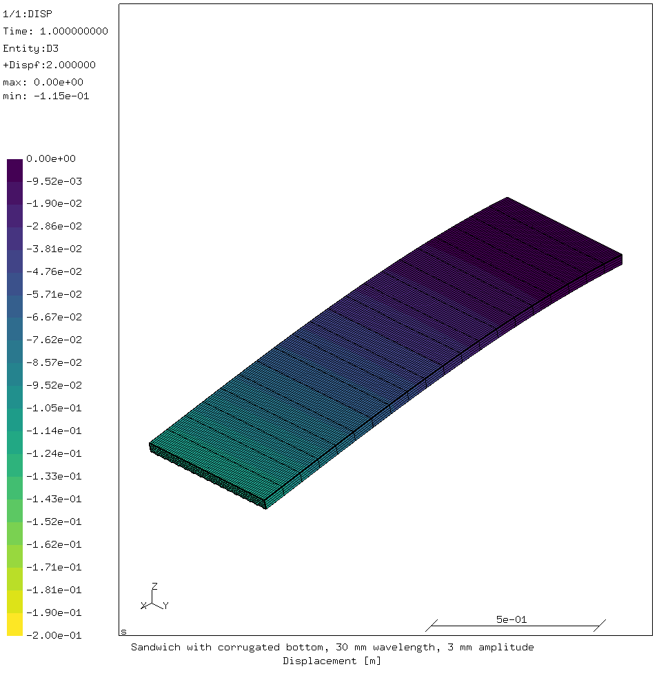
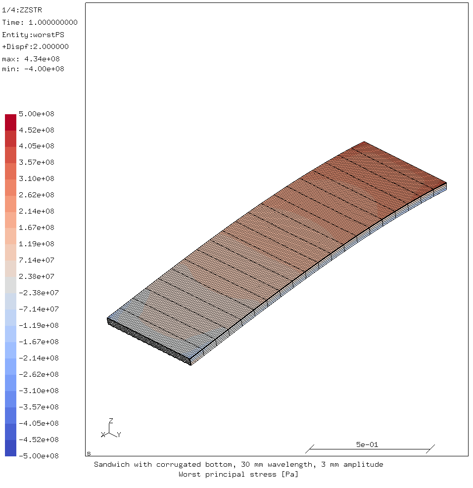
Displacement and stress results:
| displacement | -114.93 | mm |
| compression stress | -399 | MPa |
| compression stress factor | 2.82 | |
| tensile stress | 431 | MPa |
| tensile stress factor | 4.97 | |
| buckling factor | 2.95 |
Here as well the laminate will probably fail in compression before buckling occurs.
With a smaller wavelength, a smaller amplitude is sufficient to reach a high enough buckling factor.
Conclusion
A corrugated laminate on the compression side of a sandwich can significantly improve the buckling strength. It is possible to make the calculated buckling strength at least equal to the pure compression strength of the laminate.
A sandwich with the corrugated bottom is less stiff than the sandwich with a flat bottom of the same total thickness. This is to be expected:
- Most of the bottom laminate is closer to the top laminate, which means a reduced second area moment and so a reduced geometric stiffness.
- The corrugated side needs some ±45° fibers to increase its shear stiffness. This decreases the longitudinal material stiffness.
For the sandwich in question (34 mm thick, 2 mm skins), several different corrugations were proven suitable in this way;
- 60 mm wavelength with an amplitude of 5 mm.
- 30 mm wavelength with an amplitude of 3 mm.
There is clearly a correlation between the wavelength and amplitude; larger wavelengths require larger amplitudes. Approximately, the amplitude should be 10% of the wavelength.
From a standpoint of manufacturing, longer wavelengths are going to be easier than shorter ones. However, from the standpoint of x-ray image quality, lower amplitudes are probably going to be preferred.
For comments, please send me an e-mail.
Related articles
- FEA with Calculix (3)
- FEA with Calculix (2)
- FEA with Calculix (1)
- Element names in Calculix
- FEA based on STEP geometry using gmsh and CalculiX