Contact analysis of a pin in a fixed sleeve
Inspired by a recent question at work, I looked at the stresses developing in a steel pin when it is loaded under bending and partially placed in a fixed sleeve.
This is a so-called contact problem, where stresses arise because two or more bodies are in contact with each other. This is by definition a nonlinear analysis.
Since the preprocessor file is rather large, it is linked rather than incorporated: pre.fbd.
The mesh is shown below;
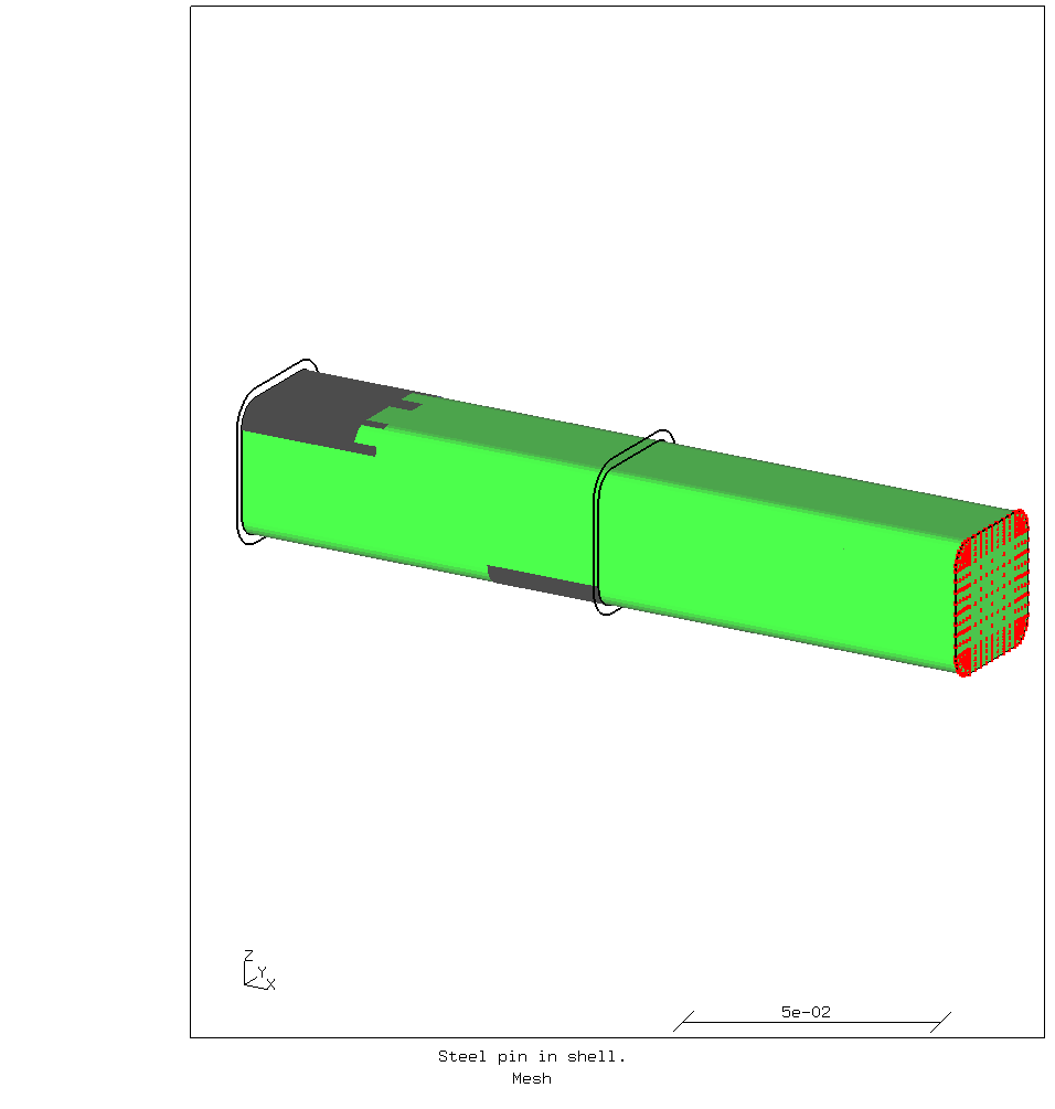
The pin with its contact patches is shown. To make that possible, only the outlines of the sleeve is shown. The sleeve of course has contact surfaces opposed to those on the pin. There is nominally 0.1 mm space between the pin and the sleeve. The nodes shown in red form the rigid body constraint where the load is applied. Only the reference node which is the point where the load is applied is not shown. It is located on the centerline of the pin but significantly in front of it.
To keep the analysis simple, no *PLASTIC properties for the material were
activated in this calculation.
The input file for the solver is also linked: job.inp.
Initially, I tried to apply a load to the rigid body constraint. However, when loaded this way, the calculation did not converge.
So the “load” was instead applied as a prescribed displacement in the -Z
direction inside the *STEP.
These kinds of calculations generally do not have a problem converging.
To check whether the correct load is reached, the reaction forces in the rigid
body nodes are saved as well.
The forces in the Z-direction are summed and printed at the end of the run by
a Python script.
It is invoked as follows:
python force.py job.dat Nload z
The contents of the script are shown below.
import sys

filename = sys.argv[1]
if not filename.endswith(".dat"):
    print("ERROR: input file name must end in '.dat'.", file=sys.stderr)
    sys.exit(1)
setname = sys.argv[2].upper()  # Set names are in upper case in the dat-file.
IX = {
    "x": 1,
    "y": 2,
    "z": 3,
}
try:
    index = IX[sys.argv[3].lower()]
except KeyError:
    print("ERROR: index must be in (x,y,z)", file=sys.stderr)

state = None  # Not reading
force = 0.0
with open("job.dat") as datfile:
    for ln in datfile:
        if "set" in ln:  # Report header
            state = None  # Only some sets are read
            if "forces" in ln and setname in ln:
                state = "read"
            continue
        if state == "read":
            if ln.isspace():
                # skip empty lines
                continue
            items = ln.strip().split()
            force += float(items[index])
print(f"Total force on set “{setname}” = {force:.0f} N")
The displacement is increased until the desired force is reached. The stresses in the pin in that case are shown in the images below.
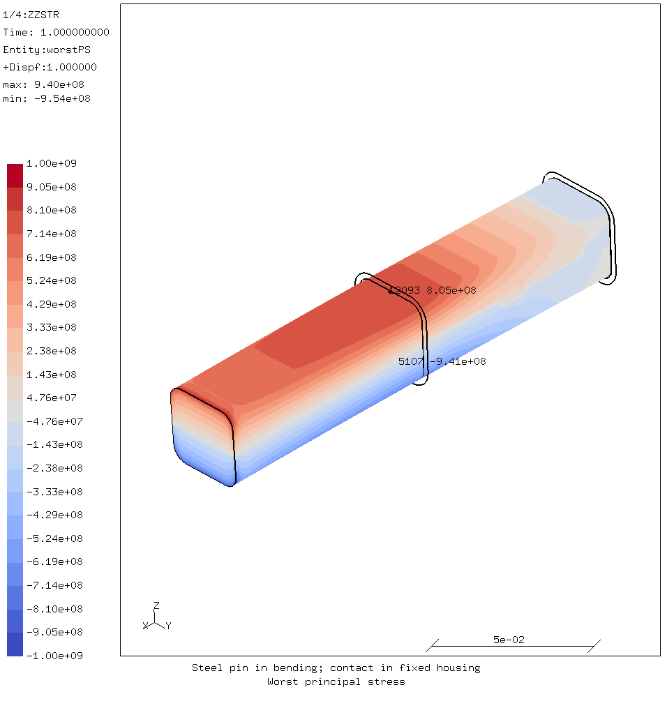
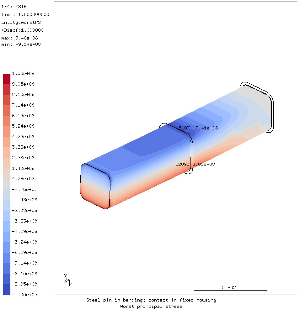
It should be noted that the apparent stress concentrations at the end of the pin where the rigid body constraint is applied are caused by that constraint. They can therefore safely be ignored.
Since the nodes of the sleeve are fixed, it has effectively an infinite stiffness. This means that the stresses in the pin are likely to be somewhat higher than in reality.
Clearly, the middle of the pin where it rests on the end of the sleeve is the critical point w.r.t. stresses. The part of the pin loaded in compression contacts the end of the sleeve. It is there where the highest stress occurs because it is subject to both bending and bearing loads.
The back end of the pin, which contacts the top of the sleeve is only lightly stressed, because it is not subject to bending stress.
Because of the application, stainless steel was required for the pin. This analyis made clear that AISI 304 would not suffice, and a high-strength duplex steel would be required.
For comments, please send me an e-mail.
Related articles
- Element names in Calculix
- FEA based on STEP geometry using gmsh and CalculiX
- Reading CalculiX mesh with Python
- Corrugation against buckling
- Approximating elliptical arcs in CalculiX Graphics