Hex versus tet meshes in FEA
In this article the difference in the images of the stresses between a quadrilateral hexahedron (“hex”) mesh and a tetraeder (“tet”) mesh will be investigated. In both cases, second order elements will be used.
Hopefully this will make it clear to the reader why hex meshes are generally preferred.
The plate with a hole that was the subject of a previous article will again be used. The analyses will be done using CalculiX.
Both analysis use approximately the same number of elements.
he hex mesh is made out of second order hex elements with reduced integration. These are called “he20r” in the pre-/post-processor and “C3D20R” in the solver.
The tet mesh is made out of second order tet elements. These are called “te10” in the pre-/post-processor and “C3D10” in the solver.
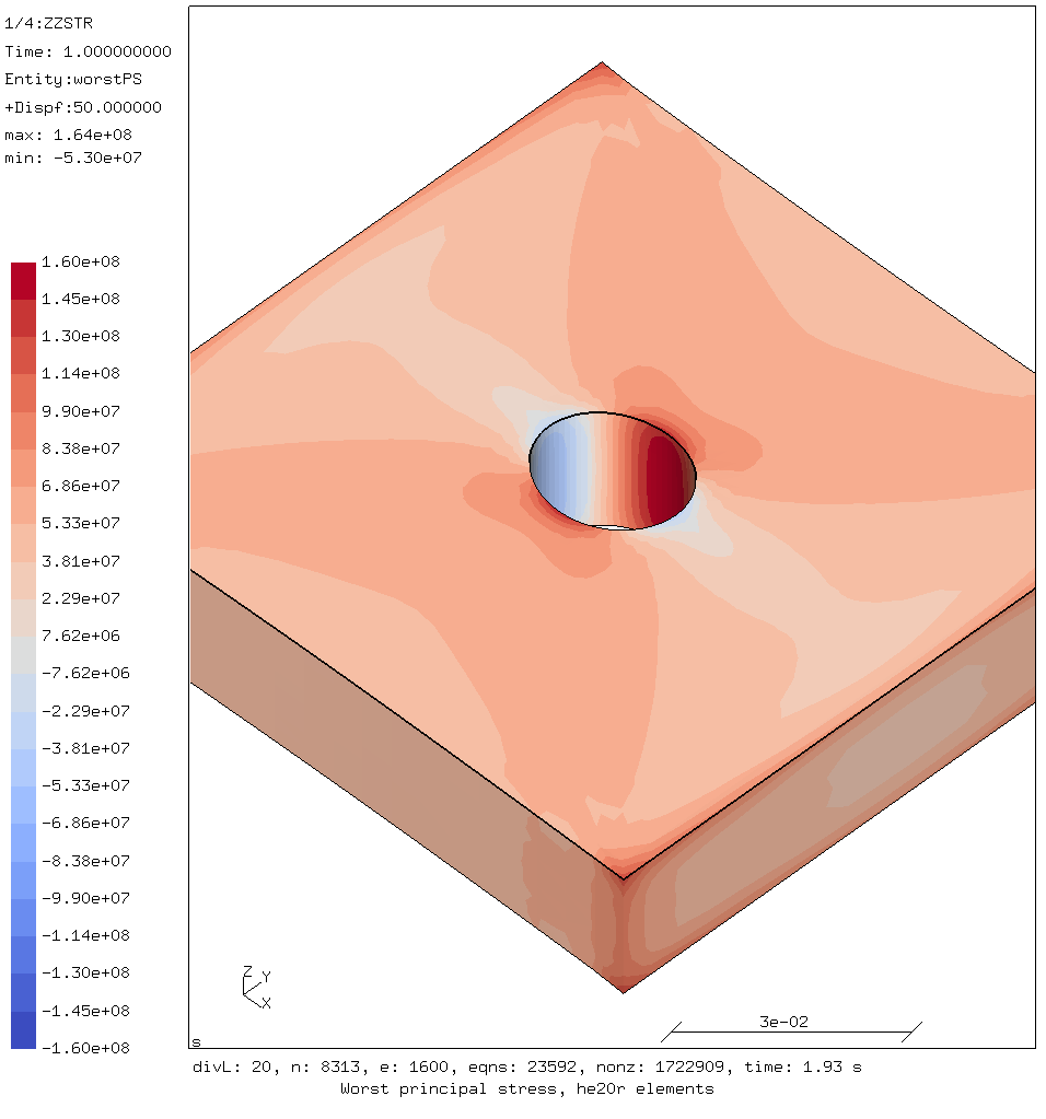
Worst principal stress using hex elements
The result generated with a hex mesh look nice and symmetric as is to be expected. Note that the whole plate was simulated, even though because of symmetry 1/4 of the plate would in theory be enough.
The largest worst principal stresses around the hole are:
- tensile stress = 164 MPa
- compression stress = -53 MPa
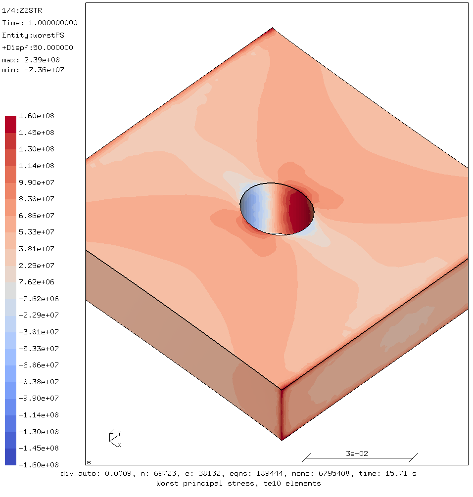
Worst principal stress using tet elements as generated by tetgen
The image produced by the tet mesh looks similar at first but the borders between the bands of different colors that indicate stress levels look blotchy and imprecise.
The largest worst principal stresses around the hole are:
- tensile stress = 182 MPa
- compression stress = -71 MPa
Making the elements smaller does not significantly reduce the maximum stress.

Worst principal stress using tet elements as generated by gmsh
Another tet mesh was generated by gmsh. This is shown above.
The largest worst principal stresses around the hole are:
- tensile stress = 179 MPa
- compression stress = -63 MPa
The reason for the differences becomes clear when the mesh is overlaid on the stress results.
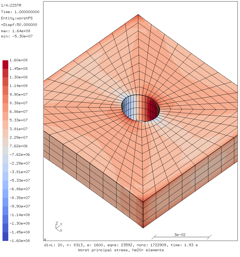
Worst principal stress showing the hex mesh
The hex mesh looks regular because it is.
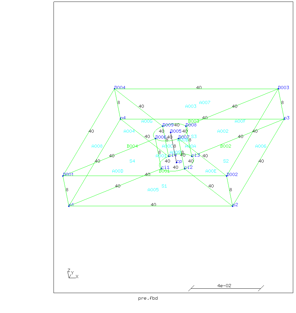
Geometry used for creating the hex mesh
The geometry was cut up into four parts with equal divisions in opposing
lines.
The cut lines run from the corner of the square to the edge of the
circle
This way, each 1/4th of the plate is quadrilateral so that cgx‘s hex
mesher can easily create a regular mesh grid.
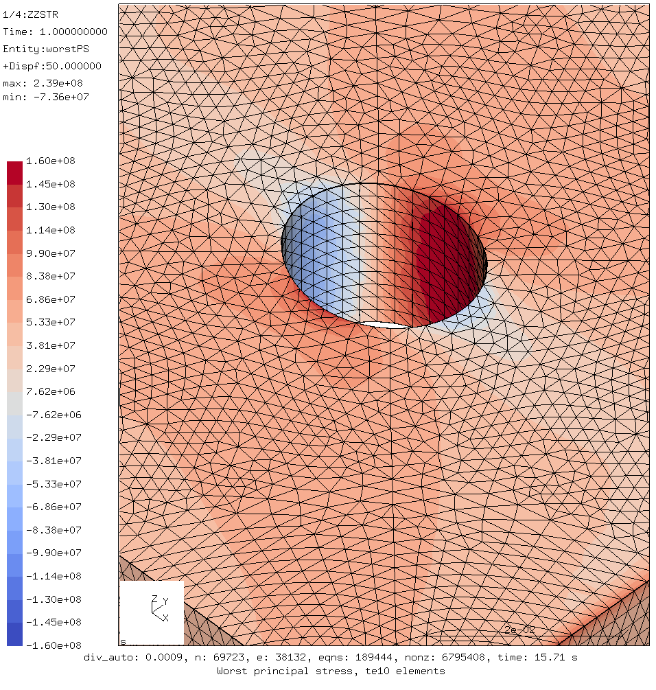
Worst principal stress showing the tet mesh made by tetgen
The tet mesh is made by an automatic mesher (tetgen)
Automatic meshers using tetrahedra can fill almost any geometry.
Bus as can be seen in the picture above, the mesh is not regular and that
shows in the results.
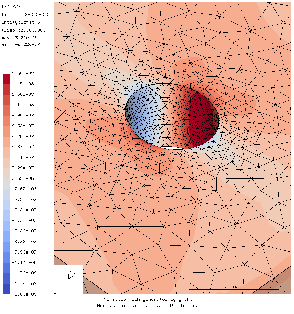
Worst principal stress showing the tet mesh made by gmsh
The other mesh was generated by (gmsh). It has a varying element size,
having smaller element around the curved surfaces.
Again the mesh is not regular around the hole.
In the tet meshes, the colors showing the stress ranges following the element boundaries. This follows from how the finite element method works. Using the loads and constraints and the global stiffness matrix, the displacement of the nodes is calculated. Stresses and strains inside each element are calculated from those displacements using the shape functions of the element. The stresses and strains are most accurate in the integration points within each element. But they are extrapolated out to the nodes and saved there because the nodes are part of the geometry and the integration points are not.
So the distribution of the nodes will influence the image; an unstructured tet mesh will effect how the stresses look locally more than a regular hex mesh
Therefore if it is preferable to use a regular mesh if possible, and it can be easier to generate regular meshes using hex elements.
For example the tra option of the swep command in CalculiX GraphicX
(which is basically an extrude operation) creates nice regular hex meshes by default.
Note that while the gmsh mesher can create hex elements, those are
generally not regular.
So those meshes exhibit similar influence on images of stress and strain.
This is reflected in the manual of the CalculiX solver. In the section covering second order hex elements with reduced integration (which are called C3D20R there) it says:
The element behaves very well and is an excellent general purpose element (if you are setting off for a long journey and you are allowed to take only one element type with you, that’s the one to take)
The section covering second order tet elements (C3D10) says:
The element behaves very well and is a good general purpose element, although the C3D20R element yields still better results for the same number of degrees of freedom. The C3D10 element is especially attractive because of the existence of fully automatic tetrahedral meshers.
For comments, please send me an e-mail.
Related articles
- Element names in Calculix
- FEA based on STEP geometry using gmsh and CalculiX
- Reading CalculiX mesh with Python
- Corrugation against buckling
- Approximating elliptical arcs in CalculiX Graphics