Singularities versus stress concentrations in FEA
The way FEA works can lead to concentrations of high stress in single elements or even nodes. This article aims to show how such singularities can be recognized and when they can be safely ignored.
Introduction
One of the aims of FEA is usually to detect the areas of high stress in a part to make sure the stresses do not exceed the maximum safe stresses for the material in question.
However, not all high stresses that can be seen looking at the stress image are real. Especially suspect are high stresses that occur in a single element or even a single node. Especially when they are found at edges or corners.
The best way to recognize singularities is to decrease the size of the elements repeatedly. A real stress concentration will at some size stop increasing in magnitude. If the stress in a single element or node keeps rising when the element becomes smaller, that is a sure sign of a singularity.
To show this, a test geometry in the form of a plate with a hole in it has been created. The simulated material is EN-AW 5754 aluminium. In the analysis, the part will be clamped at one side, and a force will be applied to the opposite side. This should produce real stress concentrations around the hole. In subsequent iterations the elements will be made smaller and smaller and observe the stresses at three points.
The stresses at three points are shown in the stress result images below. Those will be looked at them in detail later.
- The middle of the side of the hole in the plate. This is a genuine stress concentration.
- The corner of the side where the load is applied.
- The center of the side where the load is applied, as a contrast to the corner.
Mesh
Below is a picture of the initial mesh. The mesh consist of 20-node quadrilaterally-faced hexahedron elements, a.k.a. “hex” or “brick” elements. These do not only have nodes at the corners but also in the middle of the edges. That makes them “second order” or “quadratic” elements. For mechanical analysis of three dimensional objects this kind of element generally gives the best results.
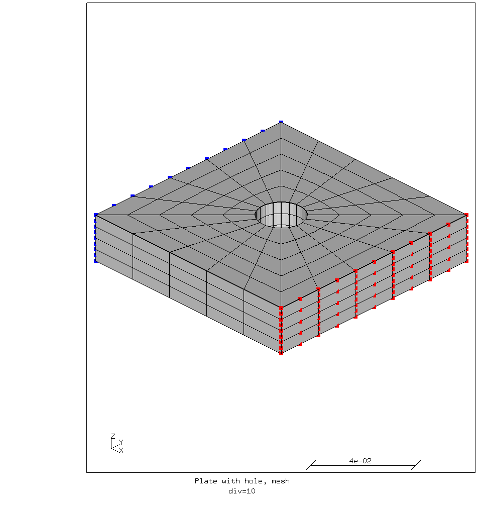
Coarse mesh of the plate with the hole.
The blue nodes are fixed, and the force is applied to the red nodes via a “rigid body” constraint. That means that all the nodes in the rigid body move as one, but the distances between them do not change. The fixed nodes do not move at all. That means that in the simulation these planes are effectively infinitely stiff. It should be acknowledged that this is simply not possible in reality.
Analysis
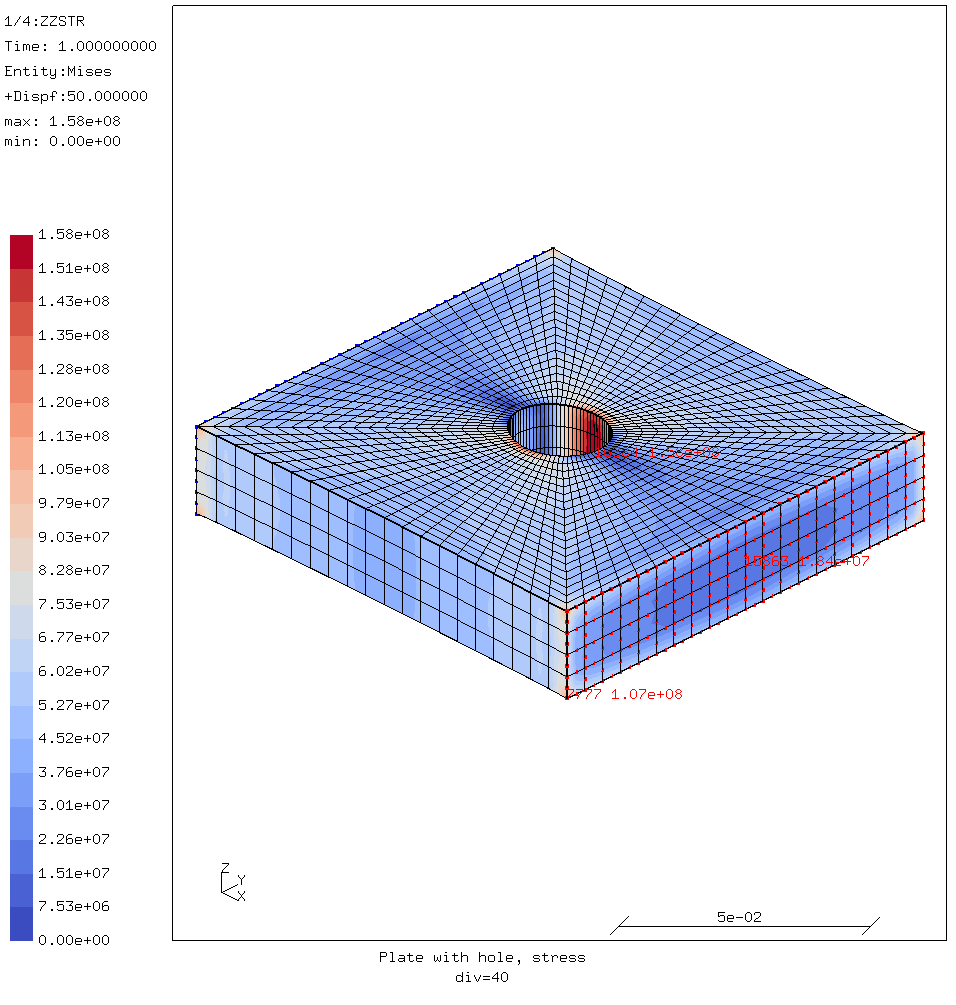
The figure below is the result of the first analysis.
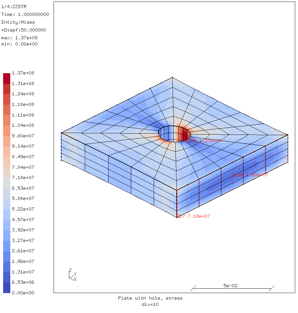
First step, stress over a coarse mesh of 2181 elements.
There is a clear stress concentration in the sides of the hole. This is as one would expect. It is worth noting that this is spread out over several elements.
There is also a stress gradient visible in the load plane. This is also to be expected because of the Poisson effect; the part is stretched in one direction, so it will contract in the other directions because of the Poisson constant of the aluminium. However most of that is concentrated at the edges of the outside elements. That will become more clear in the following steps. And that makes it suspect.
With every subsequent step, the number of elements approximately quadruples. The geometry, materials, loads and boundary conditions are kept the same. The amount of elements is the only change from step to step.
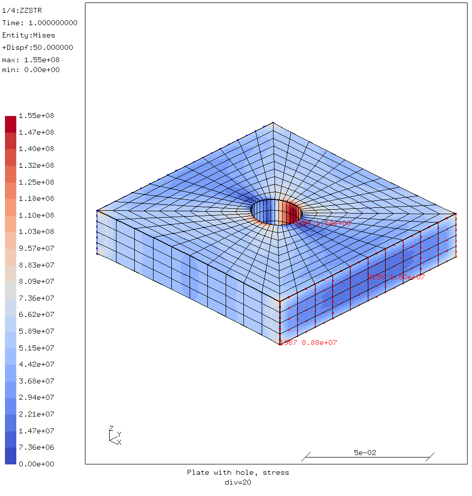
Second step, stress over a mesh of 8161 elements.
In the picture below the stress gradient over the middle of the load face is shown for the second step.
Stress gradient on the load face with a mesh of 8161 elements.
Looking from the center of the load face towards the viewer, the stress increases slowly. But over the last element the stress more than doubles and that makes it suspect. Plotting the stresses over the y-coordinate this is even more clear.
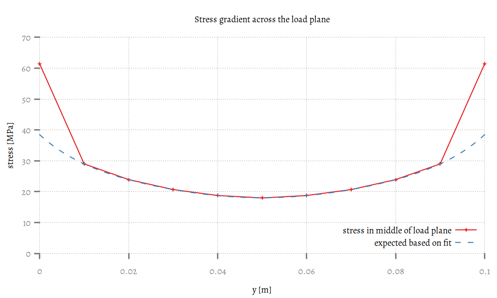
Stress gradient graph on the middle of the load plane.
The actual values are shown in red. The blue dashed line is what one would expect based on fitting a curve over all but the outer data points. One would reasonably expect the stress at the edge to be around 38 MPa, not 61 MPa!
Moving on;
Third step, stress over a mesh of 31521 elements.
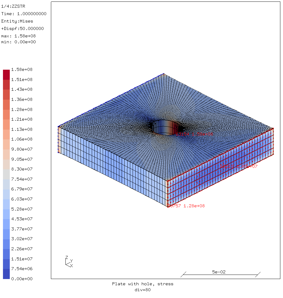
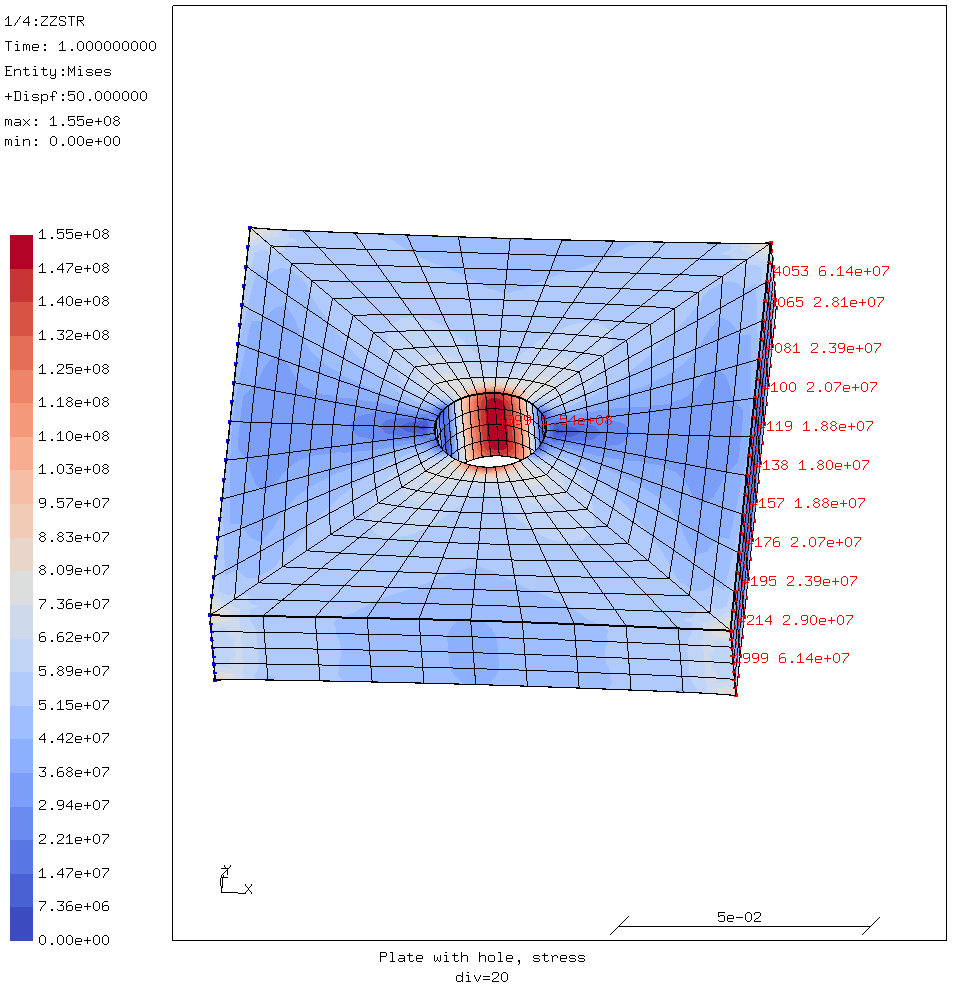
Fourth and last step, stress over a mesh of 123841 elements.
In the later images it is clear to see that the stress on the edges of the load face and especially in the corners keeps rising. It is also apparent that these high stresses are not more that one element wide, and are concentrated in one edge. Or in the case of the corners, one node.
The stresses in the three points labelled in each step are graphed below.
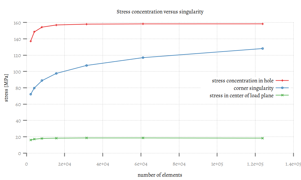
The stress in the middle of the hole quickly converges to around 158 MPa. The stress in the middle of the load surface also converges to around 18 MPa.
But the stress in the corner of the load plane keeps rising. This is the hallmark of a singularity. It is an artefact of the geometry and the way FEA works. Therefore it can simply be ignored.
If necessary, a more realistic value can be approximated by looking at the points outside the singularity and extrapolate.
Conclusions
- If an area of high stress is spread out over multiple elements, it is not a singularity.
- If the high stress is limited to a single element or even a single edge or corner it is probably a singularity.
- The hallmark of a singularity is that the stress peak keeps increasing when the elements become smaller and it doesn’t converge.
There is an exception to the first rule. If there is a stress concentration centering on one node that connects several elements then this is a singularity. This is effectively a point load or point constraint which is a type of singularity that has not been covered here.
For comments, please send me an e-mail.
Related articles
- Element names in Calculix
- FEA based on STEP geometry using gmsh and CalculiX
- Reading CalculiX mesh with Python
- Corrugation against buckling
- Approximating elliptical arcs in CalculiX Graphics